Induction Furnace Foundation Design — Key Considerations
An induction furnace foundation is not a standard civil work item. It is a precision structural element that must perform reliably under vibration, heat, electromagnetic effects and the static dead load of equipment that can weigh hundreds of tonnes.
Why Furnace Foundations Are Different
Most civil foundations carry static loads — the weight of a column, a wall or a slab. An induction furnace foundation carries all of that, plus dynamic loads generated by the furnace operation itself. Induction furnaces produce vibration through their power systems, the movement of molten metal, and the hydraulic tilting mechanisms used during tapping.
If a foundation is not designed for these dynamic loads, it will experience differential settlement, cracking and — over time — failure. Repairs on a furnace foundation inside a live steel plant are expensive and disruptive. Getting it right the first time is essential.
Key Design Considerations
1. Dynamic Load Analysis
Before any reinforcement is detailed, the dynamic characteristics of the furnace need to be understood. This includes the operating frequency of the power supply, the mass of the furnace and shell, and the tilting mechanism forces. The foundation natural frequency must be tuned away from the operating frequency to avoid resonance.
2. Depth and Bearing Capacity
In Marathwada, including Jalna, the subsoil is predominantly Deccan basalt — a hard rock formation that offers excellent bearing capacity when reached. The challenge is depth: furnace loads are heavy enough that foundations often need to go deeper than typical commercial foundations to reach competent rock or to spread load adequately.
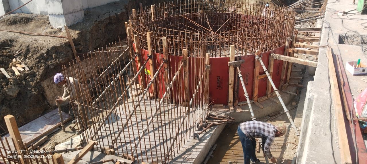
3. Reinforcement Density
Furnace foundations typically require heavily reinforced concrete — both for structural strength and to resist cracking under thermal cycling. The reinforcement cage must be precisely positioned, cover maintained with proper spacers, and concrete placed carefully to avoid segregation in dense steel sections.
4. Thermal Effects
Although the furnace shell is insulated, heat transmission to the foundation over time causes thermal expansion and cycling. Isolation joints, appropriate concrete mixes with low heat of hydration, and thermal barriers are design tools used to manage this.
5. Anchor Bolt Layout
Furnace equipment is bolted to the foundation with anchor bolts whose position is critical — they must align precisely with the equipment supplier's baseplate drawings. Errors in anchor bolt position cause installation delays and can require expensive remedial work. Surveying anchor bolt positions before pour is non-negotiable.
Execution on a Live Plant Site
Most induction furnace foundations are constructed in phases within operating steel facilities. Excavation, dewatering, blinding, reinforcement, formwork and pour all happen in an environment where other production activity continues nearby.
This requires careful site planning: segregating work zones from plant operations, managing concrete pour schedules around production shifts, and ensuring reinforcement and formwork don't interfere with equipment movement.
KKB Group's Experience
KKB Group has delivered induction furnace foundation packages across Maharashtra's steel sector, including a 40-tonne furnace foundation executed in a live plant environment in Jalna. The combination of in-house engineering through ARK Workspace, execution through KKB Associates, and concrete supply from Jugal Infra's Ultratech-operated RMC plant means every element of the package is controlled by one team.
Have a project in Jalna or Maharashtra?
KKB Group delivers EPC construction, ready mix concrete supply and design consultancy across Maharashtra. Contact us to discuss your requirements.